
1) Create your first patch
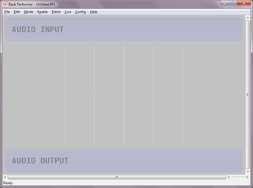
- Start with a new document
For our first patch we are going to start with a new document. Launch the application and press Ctrl+N to create a new file (or in the "file" menu, select "new")
- Create the master module
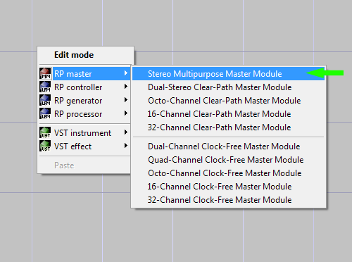
In order to produce sound, every patch needs a master module, and there can be only one per document. Master modules are a special class of modules that represent your sound card audio inputs and outputs inside the application.
The type of master module you use determines how many physical audio channels can be used by the patch. For this example we are going to use a simple stereo master module. Right-click on the background of the patcher and select "RP master" then "Stereo Multipurpose Master Module".
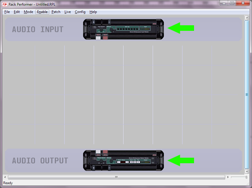
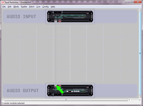
Notice how the two parts of the master module appeared in the patcher. The top part allows to use your sound card stereo input and the bottom one is for your stereo output.
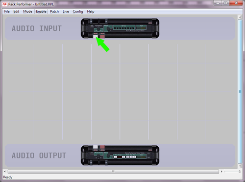
- Create an audio link
Now patch the left input channel to the left output channel. For this, click on the left port of the top master module half, and hold your click:
Then drag the mouse cursor to the left port of the bottom master module half:
Finally release the mouse button, and a patch link will be created:
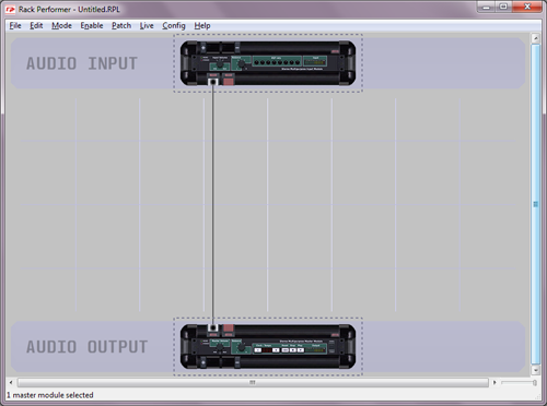
- Enable power
What we did is the simplest possible patch in Rack Performer: we just connected your sound card audio input directly to your audio output. And because we used only one channel, both will be opened in "mono" mode.
Now we're going to enable power. In order to prevent any nasty feedback or loud volume, please verify beforehand that your sound card output volume and/or external amplification are not too high. When you are ready, press F12 to enable power (or use the "enable" menu)
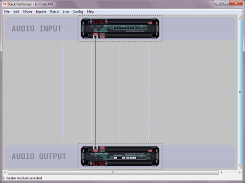
Notice how the power status is reflected in the patcher. At this point if your machine has a microphone (ex: laptops) or if you have a sound source connected to your sound card input, you should be able to hear it on your sound card output.
Note: if you don't hear any sound at this step, first make sure that you have an integrated microphone or a live source connected to your sound card audio input. If you get warning messages please refer to the user manual and the support forums to properly setup your audio settings first.
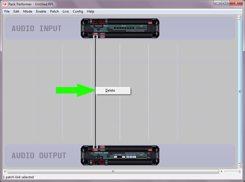
- Delete the audio link
Now we are going to create another patch, this time producing sound by itself and not using the audio input. Delete the audio link that you created by right-clicking on it and selecting "delete":
- Create a test generator module
Now add a simple test generator module by displaying the patcher context menu and selecting "RP generators" then "Signals / Oscillators" and finally "Sin Test-Gen Mk2":
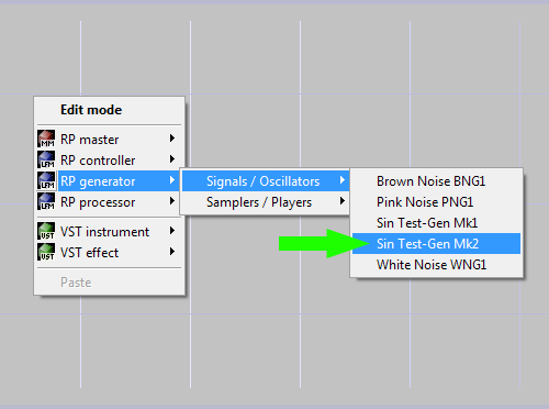
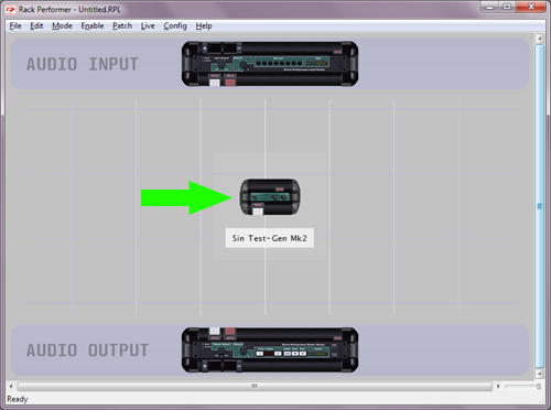
Notice where the new module has been added. Generators can produce sound by themselves. Instruments fall into this class. Some generators can have multiple outputs, and some even have inputs. This one has a single mono output.
- Connect the generator to the master module
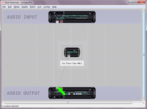
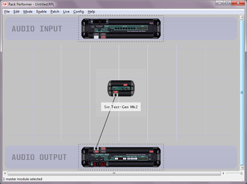
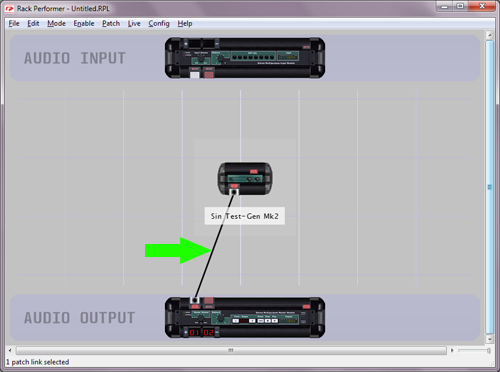
Now create a patch link between the generator output and the left master module port down below. Generators must have at least one of their outputs connected in order to be powered on.
- Enable power again
Let's enable power again. This time you should hear a continuous 440 Hz tone, similar to those used to tune instruments:
- Delete the audio link (alternative way)
Now click on the audio link to select it, and press the delete key: this is another way to delete links.
- Create a stereo pan module
As we have seen, signal flows from the top of the patcher to the bottom. The output of the test generator went down to the input of the master module, which in turns forwarded it to your sound card output.
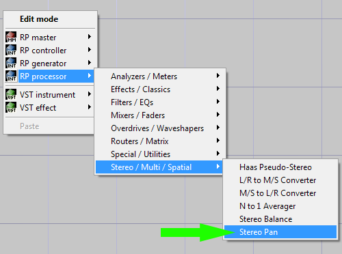
We are going to insert another module between them. Display the patcher context menu and this time create a "Stereo Pan" module:
- Decrease input bundle size
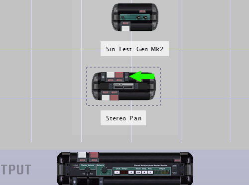
As you can see, this module is a processor: it has audio inputs on the top and audio outputs on the bottom. Processors need an input signal to work. If none of their inputs are connected, they will not be powered on. Also, like generators, they need at least one connected output.
This processor has a stereo input and a stereo output. Furthermore its input has small "plus" and "minus" buttons around it, meaning it is a variable size bundle. As we are going to plug a mono source into it (our test generator has only a mono output) we can decrease the size of the bundle by clicking on the "minus" button:
- Patch the two modules together
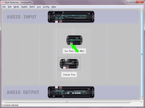
Now create an audio link starting from the stereo pan input to the test generator ouput. Notice how patch links can be created in this direction too, as long as you connect one input to one output (connecting input to input or output to output is not allowed)
- Connect the pan to the master module
Then connect the stereo pan outputs to the master module below. This time we are going to connect the two channels, and the sound card will be opened in stereo mode.
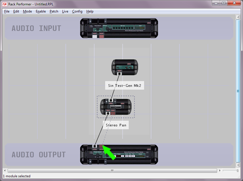
- Add one LFO module to the patch
For extra fun we are going to add another module to the patch, this time in the controllers class. Display the patcher context menu and select "RP controllers" then "RoboControl / Automation" and finally "RBC LFO":
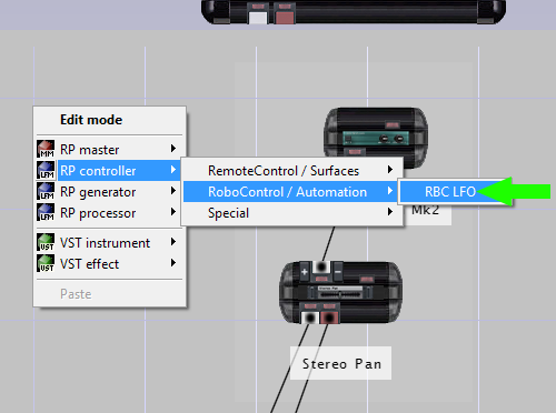
Notice how this module has no audio ports. Controllers are a special class of modules that do not process audio but rather deal with control signals, like sequencing, automating etc. The one we created is a low frequency oscillator able to modulate any control port in the patch.
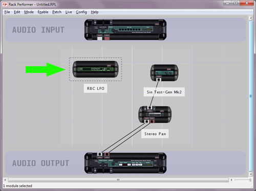
- Duplicate the LFO module
Click on the LFO module and press Ctrl+C then Ctrl+V on your keyboard to duplicate it. You can add any number of modules to your patch (i.e multiple instances of the same module are allowed) The only limitation is for the master module, which is always single.
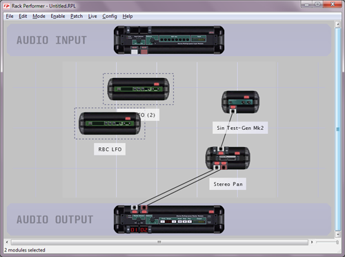
You can enable power again, our small patch is ready.
2) Edit your first patch
- Switch to edit mode
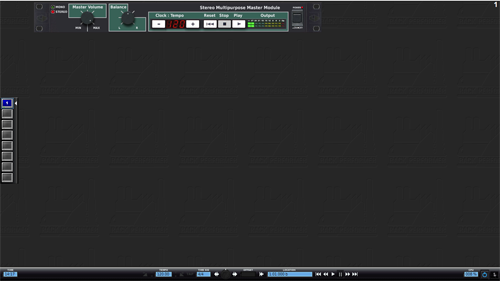
Enter edit mode by pressing Tab. You should see the master module GUI already pre-dispatched for you:
- Dispatch all module GUI's
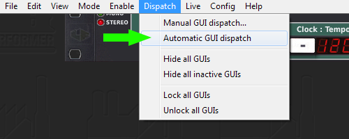
We are going to dispatch the GUI's of the modules we created. In the "dispatch" menu, select "automatic GUI dispatch":
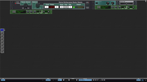
Notice how the GUI's of our 4 modules appeared. The small light-green one is our test generator, the grey one with a horizontal fader control is the stereo pan and the two other ones are the LFO's:
- Play with the generator and the pan controls
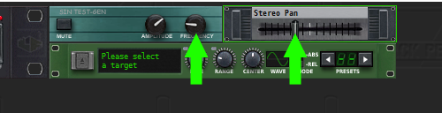
To get a better idea of what module is doing what, play with the generator frequency and amplitude controls as well as the pan control:
- Assign the first LFO to the generator frequency
Now we are going to assign the first LFO target, for that click on the select button of the LFO:
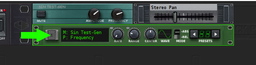
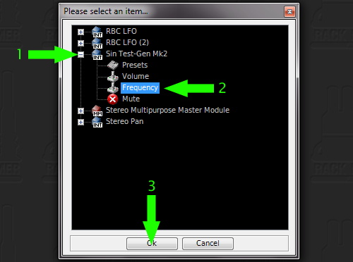
In the selection dialog that pops up, select the test generator frequency as target:
- Play with the LFO controls
Have some fun by playing with the LFO parameters and see how it modulates the test generator:
- Assign the second LFO to the pan
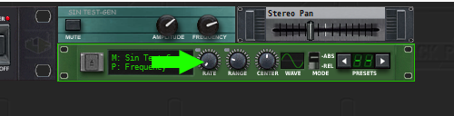
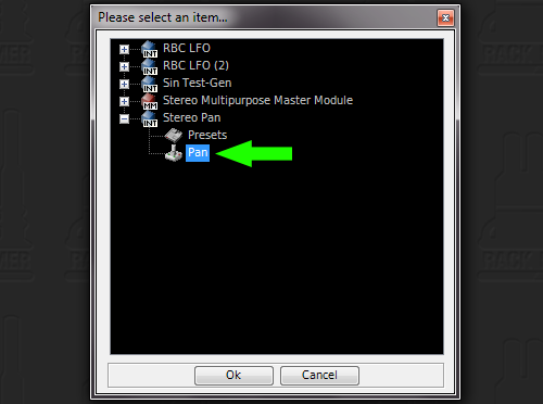
Then you can assign the second LFO to the stereo pan, creating an auto-pan effect:
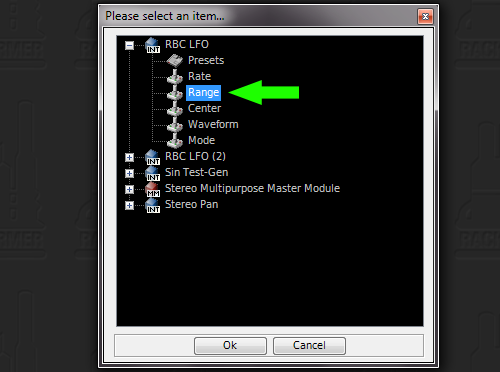
- Re-assign the second LFO to the first LFO range
Finally, change the second LFO target, and this time select the first LFO "range" control port, creating a more complex modulation.
Notice that the LFO can switch targets on the fly and thus one single controller can be used to automate different targets (and it is even simpler when you start using module presets)
Congratulations! You just made your first patch in Rack Performer!
- Start with a new document
For our first patch we are going to start with a new document. Launch the application and press Ctrl+N to create a new file (or in the "file" menu, select "new")
- Create the master module
In order to produce sound, every patch needs a master module, and there can be only one per document. Master modules are a special class of modules that represent your sound card audio inputs and outputs inside the application.
The type of master module you use determines how many physical audio channels can be used by the patch. For this example we are going to use a simple stereo master module. Right-click on the background of the patcher and select "RP master" then "Stereo Multipurpose Master Module".
Notice how the two parts of the master module appeared in the patcher. The top part allows to use your sound card stereo input and the bottom one is for your stereo output.
- Create an audio link
Now patch the left input channel to the left output channel. For this, click on the left port of the top master module half, and hold your click:
Then drag the mouse cursor to the left port of the bottom master module half:
Finally release the mouse button, and a patch link will be created:
- Enable power
What we did is the simplest possible patch in Rack Performer: we just connected your sound card audio input directly to your audio output. And because we used only one channel, both will be opened in "mono" mode.
Now we're going to enable power. In order to prevent any nasty feedback or loud volume, please verify beforehand that your sound card output volume and/or external amplification are not too high. When you are ready, press F12 to enable power (or use the "enable" menu)
Notice how the power status is reflected in the patcher. At this point if your machine has a microphone (ex: laptops) or if you have a sound source connected to your sound card input, you should be able to hear it on your sound card output.
Note: if you don't hear any sound at this step, first make sure that you have an integrated microphone or a live source connected to your sound card audio input. If you get warning messages please refer to the user manual and the support forums to properly setup your audio settings first.
- Delete the audio link
Now we are going to create another patch, this time producing sound by itself and not using the audio input. Delete the audio link that you created by right-clicking on it and selecting "delete":
- Create a test generator module
Now add a simple test generator module by displaying the patcher context menu and selecting "RP generators" then "Signals / Oscillators" and finally "Sin Test-Gen Mk2":
Notice where the new module has been added. Generators can produce sound by themselves. Instruments fall into this class. Some generators can have multiple outputs, and some even have inputs. This one has a single mono output.
- Connect the generator to the master module
Now create a patch link between the generator output and the left master module port down below. Generators must have at least one of their outputs connected in order to be powered on.
- Enable power again
Let's enable power again. This time you should hear a continuous 440 Hz tone, similar to those used to tune instruments:
- Delete the audio link (alternative way)
Now click on the audio link to select it, and press the delete key: this is another way to delete links.
- Create a stereo pan module
As we have seen, signal flows from the top of the patcher to the bottom. The output of the test generator went down to the input of the master module, which in turns forwarded it to your sound card output.
We are going to insert another module between them. Display the patcher context menu and this time create a "Stereo Pan" module:
- Decrease input bundle size
As you can see, this module is a processor: it has audio inputs on the top and audio outputs on the bottom. Processors need an input signal to work. If none of their inputs are connected, they will not be powered on. Also, like generators, they need at least one connected output.
This processor has a stereo input and a stereo output. Furthermore its input has small "plus" and "minus" buttons around it, meaning it is a variable size bundle. As we are going to plug a mono source into it (our test generator has only a mono output) we can decrease the size of the bundle by clicking on the "minus" button:
- Patch the two modules together
Now create an audio link starting from the stereo pan input to the test generator ouput. Notice how patch links can be created in this direction too, as long as you connect one input to one output (connecting input to input or output to output is not allowed)
- Connect the pan to the master module
Then connect the stereo pan outputs to the master module below. This time we are going to connect the two channels, and the sound card will be opened in stereo mode.
- Add one LFO module to the patch
For extra fun we are going to add another module to the patch, this time in the controllers class. Display the patcher context menu and select "RP controllers" then "RoboControl / Automation" and finally "RBC LFO":
Notice how this module has no audio ports. Controllers are a special class of modules that do not process audio but rather deal with control signals, like sequencing, automating etc. The one we created is a low frequency oscillator able to modulate any control port in the patch.
- Duplicate the LFO module
Click on the LFO module and press Ctrl+C then Ctrl+V on your keyboard to duplicate it. You can add any number of modules to your patch (i.e multiple instances of the same module are allowed) The only limitation is for the master module, which is always single.
You can enable power again, our small patch is ready.
2) Edit your first patch
- Switch to edit mode
Enter edit mode by pressing Tab. You should see the master module GUI already pre-dispatched for you:
- Dispatch all module GUI's
We are going to dispatch the GUI's of the modules we created. In the "dispatch" menu, select "automatic GUI dispatch":
Notice how the GUI's of our 4 modules appeared. The small light-green one is our test generator, the grey one with a horizontal fader control is the stereo pan and the two other ones are the LFO's:
- Play with the generator and the pan controls
To get a better idea of what module is doing what, play with the generator frequency and amplitude controls as well as the pan control:
- Assign the first LFO to the generator frequency
Now we are going to assign the first LFO target, for that click on the select button of the LFO:
In the selection dialog that pops up, select the test generator frequency as target:
- Play with the LFO controls
Have some fun by playing with the LFO parameters and see how it modulates the test generator:
- Assign the second LFO to the pan
Then you can assign the second LFO to the stereo pan, creating an auto-pan effect:
- Re-assign the second LFO to the first LFO range
Finally, change the second LFO target, and this time select the first LFO "range" control port, creating a more complex modulation.
Notice that the LFO can switch targets on the fly and thus one single controller can be used to automate different targets (and it is even simpler when you start using module presets)
Congratulations! You just made your first patch in Rack Performer!